
Vimfun / Comparisons

Centrifugal Separator vs Cyclone Separator

Both can use centrifugal effects, but they generate the separating action differently. Compare a rotating-bowl coolant centrifuge with a liquid hydrocyclone on the actual solids and hydraulic duty.

Discuss Your ApplicationExplore the guide ↓

Clarify the equipment names first

The phrase centrifugal separator vs cyclone separator can be misleading because a hydrocyclone is itself a form of centrifugal separation. Here, centrifugal separator means a mechanically driven rotating-bowl centrifuge for coolant solids. Cyclone separator means a liquid hydrocyclone, not a dust cyclone operating in a gas stream.

In a rotating-bowl unit, the driven bowl produces the centrifugal field. In a hydrocyclone, the incoming liquid follows a designed swirling path through a stationary body. The feed system supplies the hydraulic conditions that create that motion. This distinction affects how each device is installed, controlled and maintained.

Ask a supplier to identify the architecture before comparing quoted performance. A broad product name does not tell you whether solids collect in a bowl, leave through an underflow or accumulate in a collection chamber for purging. Those differences matter when returning useful coolant and handling separated material.
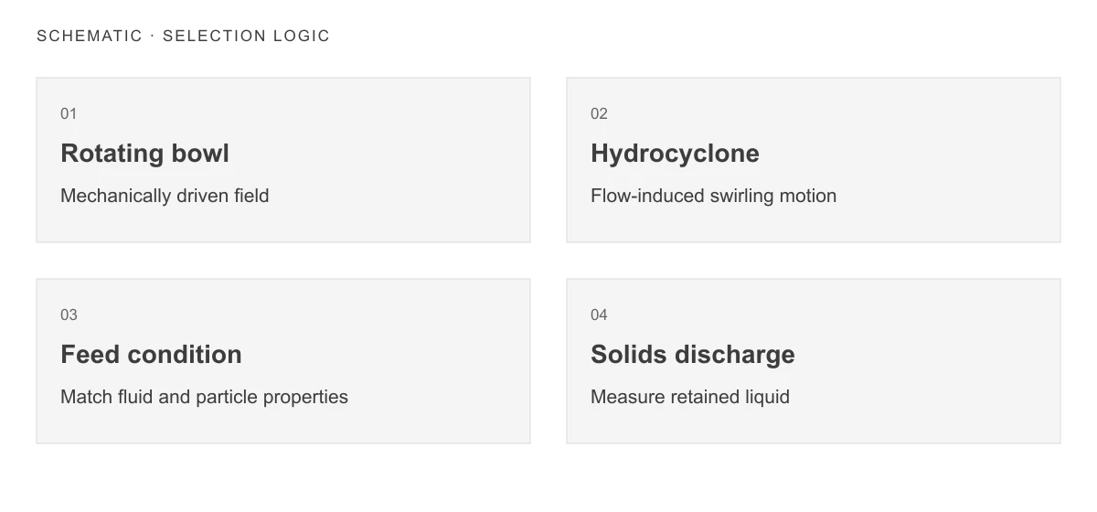
Schematic: Rotating bowl: Mechanically driven field; Hydrocyclone: Flow-induced swirling motion; Feed condition: Match fluid and particle properties; Solids discharge: Measure retained liquid.
Schematic, not a test result or an equipment drawing.

Rotating bowl → Hydrocyclone → Feed condition → Solids discharge

Compare the operating requirements

Compare the operating requirements
RequirementRotating-bowl coolant centrifugeLiquid hydrocyclone or cyclonic separator
Source of separating actionMotor-driven bowl rotationLiquid flow through designed geometry
Feed-system questionSuitable feed rate and stable delivery to the bowlRequired flow and pressure operating window
Solids-handling questionBowl capacity and cleaning or discharge sequenceUnderflow, purge or collection arrangement for that design
Main verificationCapture at actual viscosity, loading and treatment rateSeparation curve under specified hydraulic and feed conditions
Maintenance focusRotating assembly, drives and solids removalWear, blockage, valves and the associated pump
Fluid-loss checkLiquid retained in discharged materialLiquid leaving with underflow or purge

A stationary separator body does not mean the whole installation has no moving parts or energy demand. The pump and purge equipment remain part of the system. Conversely, a driven centrifuge's motor power does not describe the performance of the whole treatment circuit without feed and discharge information.

Particle properties decide whether the test is promising

Density difference, particle size and liquid viscosity influence centrifugal separation. Dense, readily settling particles are a different duty from small particles whose density is close to that of the liquid. The same machine can behave differently when the process changes from steel machining to an aluminium-bearing fluid.

LAKOS identifies greater solids specific gravity and lower liquid viscosity as favourable factors for its cyclonic separators. Its published results are product- and application-specific; they must not be used as a universal micron rating for all hydrocyclones or as a performance guarantee for a Vimfun centrifuge.

For either candidate, measure the fraction that matters to the process. If large particles dominate the feed mass, an impressive overall mass removal figure can hide insufficient control of fine particles. Request a size-resolved result where that is necessary to evaluate nozzle protection, surface finish or another defined production requirement.

Keep the hydraulic operating window visible

A hydrocyclone should be selected with its specified flow and pressure relationship, not just its pipe connection size. Ask what happens when the plant runs fewer machines, changes pump speed or switches a parallel branch. Operation outside the agreed window can change separation and the behaviour of the concentrated stream.

Some designs use a continuing underflow, while others use a collection chamber and periodic purge. Understand the proposed design rather than applying one discharge description to the entire category. Record the associated fluid loss and how collected solids are transferred or dewatered.

For a rotating-bowl centrifuge, feed rate affects the separation duty as well as throughput. Confirm the pump arrangement, interlocks and response to a full collection region or a discharge event. A manufacturer's maximum flow should not be treated as the guaranteed rate for every fine-particle target.
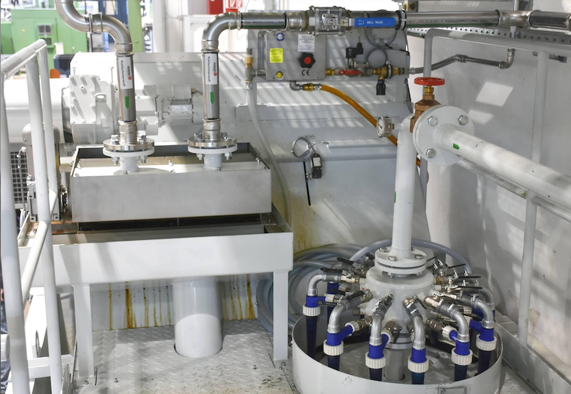
Multi-unit hydrocyclone assembly with connected feed and discharge piping
Hydrocyclone assembly and connected pipework. Installation reference; the photograph does not establish operating pressure, flow or separation performance.

Distinguish centrifugal field from treatment capacity

Use the G-value calculation guide for a rotating bowl with a known radius and speed. For alternatives outside centrifugal separation, consult the six-method filtration comparison.

A higher stated G value is not, by itself, proof of a better production outcome. The available time for separation, liquid path, solids loading and collection arrangement also matter. Two proposals should be compared using matched feed and acceptance criteria rather than a single maximum figure.

A hydrocyclone's internal field varies with position and operating conditions; it is not normally specified by a single bowl radius and mechanical rpm. Do not enter pump speed into a rotating-bowl G calculator and treat the result as hydrocyclone performance. Pump rotation and the liquid's internal motion are different quantities.

For a centrifuge, ask where the quoted field applies and what treatment flow accompanies the application result. Retain the distinction between catalogue geometry and a fluid test. The centrifuge selection guide explains the additional inputs needed for a model assessment.

Assess ownership and integration together

A suitable hydrocyclone can be attractive when the solids are readily separable and the plant can provide consistent hydraulic conditions. Check whether the existing pump has the required duty available or whether another pump is needed. Include abrasion, purge maintenance and collection infrastructure in the estimate.

A rotating-bowl centrifuge can be considered where a mechanically generated field and controlled treatment rate are worth assessing for the fines present. Include drive power, bowl cleaning, service access and the actual discharge method. It still needs feed protection against unsuitable debris and a destination for the separated material.

Compare the complete installed arrangement. A separator that fits a small floor footprint may require space for a tank, valves, pump and maintenance access. A proposed side stream should also have a feed and return arrangement that prevents immediate recirculation of already-treated liquid.

Use a paired trial to make the choice

Supply the same representative fluid description to both suppliers, including temperature, viscosity information, particle material and the operating range. Agree on sample points and what constitutes stable running. Document whether the returned fluid is suitable for reuse, rather than judging it only by colour.

For the hydrocyclone, record feed flow, relevant pressures and the purge or underflow condition during sampling. For the centrifuge, record feed rate, specified speed and time since discharge or cleaning. Collect the separated material so that retained liquid and handling requirements can also be assessed.

Repeat the comparison at realistic low and high production conditions. If the fine fraction remains above the agreed target, consider an additional barrier stage. If the main limitation is unwanted oil or fluid degradation, clarify that requirement separately; a solids-separation trial does not establish those treatment capabilities.

Choose a circuit, not a technology slogan

The appropriate outcome may be retaining the current separator, adding a polishing stage or replacing the bulk-removal stage. Record the reason for the decision in terms of treatment quality, sustained operation and total handling work. Avoid claims that one category always replaces the other.

For a broader view of the equipment category, see industrial liquid centrifugal separation. For a shared production circuit, review central coolant filtration. Send Vimfun your fluid details and existing hydraulic arrangement to assess whether a rotating-bowl solids-separation trial is appropriate.

Technical references

Sources for the specific principles identified in this guide. Manufacturer examples do not establish Vimfun performance.

Define the duty before choosing equipment

Share the fluid, contaminant, operating conditions and the result your process needs. We can then discuss the evidence and test conditions required for an application assessment.

Request an Application Review
Scroll to Top