
Products · Coolant Centrifuge

Coolant Centrifuge for Cleaner Fluid and Stable Production

Remove suspended metal fines, swarf and sludge without disposable filter media in the centrifugal separation stage.
Working mainly with neat oil?Oil viscosity, temperature and solids behaviour require a separate selection route. Use the Centrifugal Oil Cleaner guide for oil-based applications.
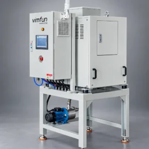
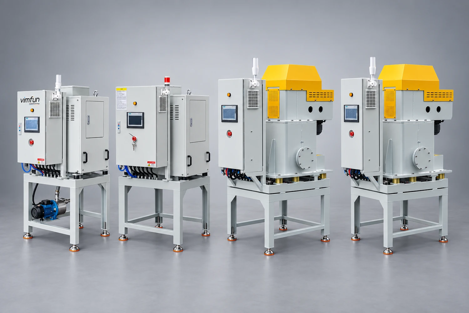
Vimfun VC series coolant centrifuges for industrial solid-liquid separation
01 · Product range

Explore VC Coolant Centrifuge Models

Open a model page for its specifications, operating fit and inquiry details. Product names, images and links below are loaded directly from WooCommerce.

02 · Start with the contamination

What Is Circulating Through Your Coolant?

Machining, grinding, rolling and forming processes continuously introduce solids into the fluid circuit. Large chips may settle or be caught by a coarse screen, but fine metallic particles remain suspended and return through pumps, valves and nozzles.

As these particles recirculate, they can settle in low-flow zones, restrict small passages and carry abrasive contamination back to the cutting area. The practical target is therefore not simply clearer-looking fluid. It is a more stable fluid circuit with less repeated exposure to dense, separable solids.

FINES

Suspended Metal Fines

Dense fine particles that settle too slowly under normal sump conditions.

SWARF

Chips and Swarf

Machining debris that requires coarse protection before fine centrifugal separation.

SLUDGE

Sump Deposits

Accumulated solids in low-flow areas increase cleaning work and fluid loss.

A coolant centrifuge targets separable suspended solids. It does not remove dissolved salts, correct coolant chemistry or separate every form of tramp oil; those conditions may require another treatment stage.
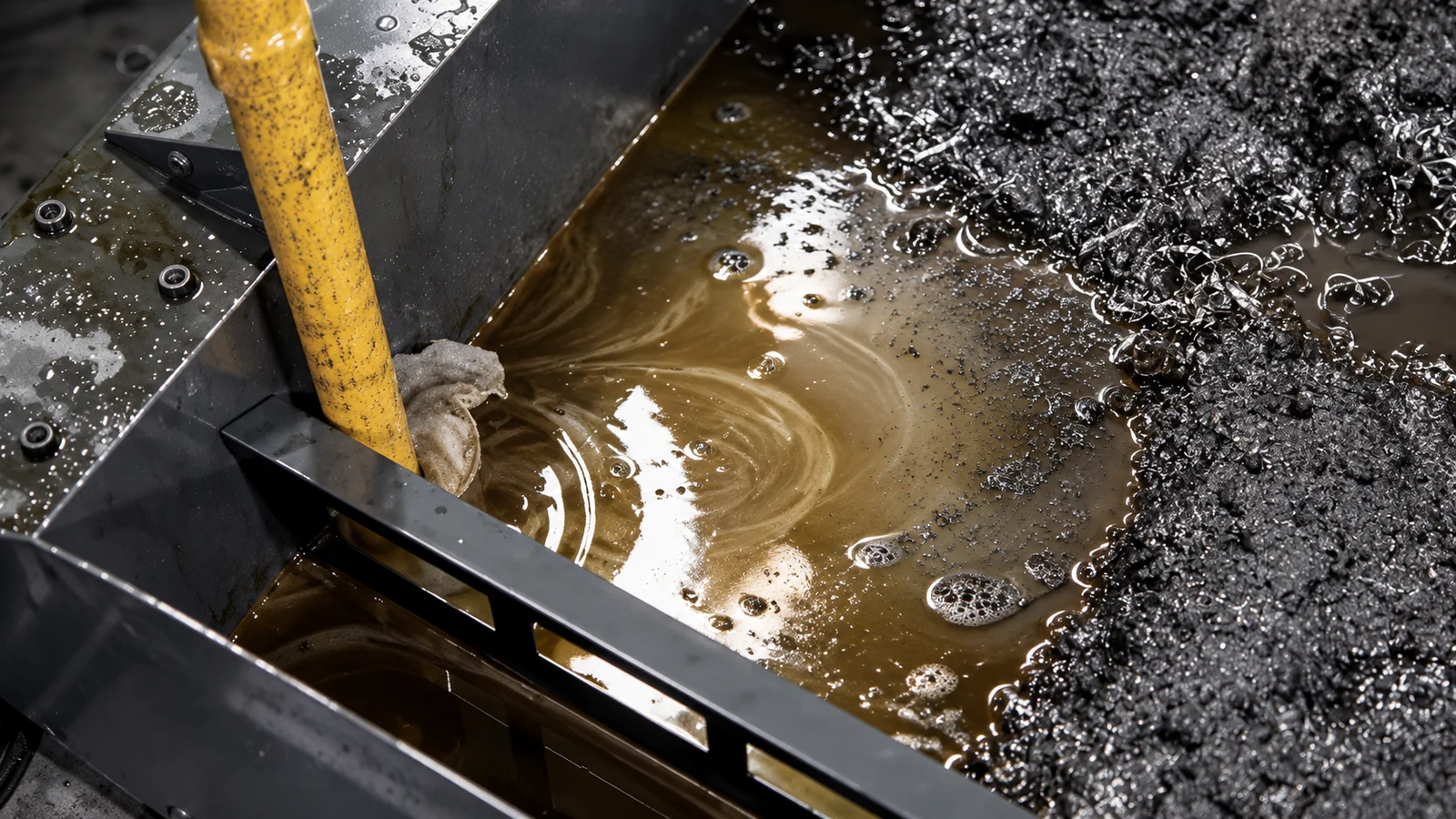
Metal swarf and dark sludge accumulated in an industrial coolant sump
03 · Solid-liquid separation

How a Coolant Centrifuge Works

Contaminated fluid enters a rotating tubular bowl. Centrifugal force moves denser solids outward while separated fluid follows the designed outlet path and returns to the sump.
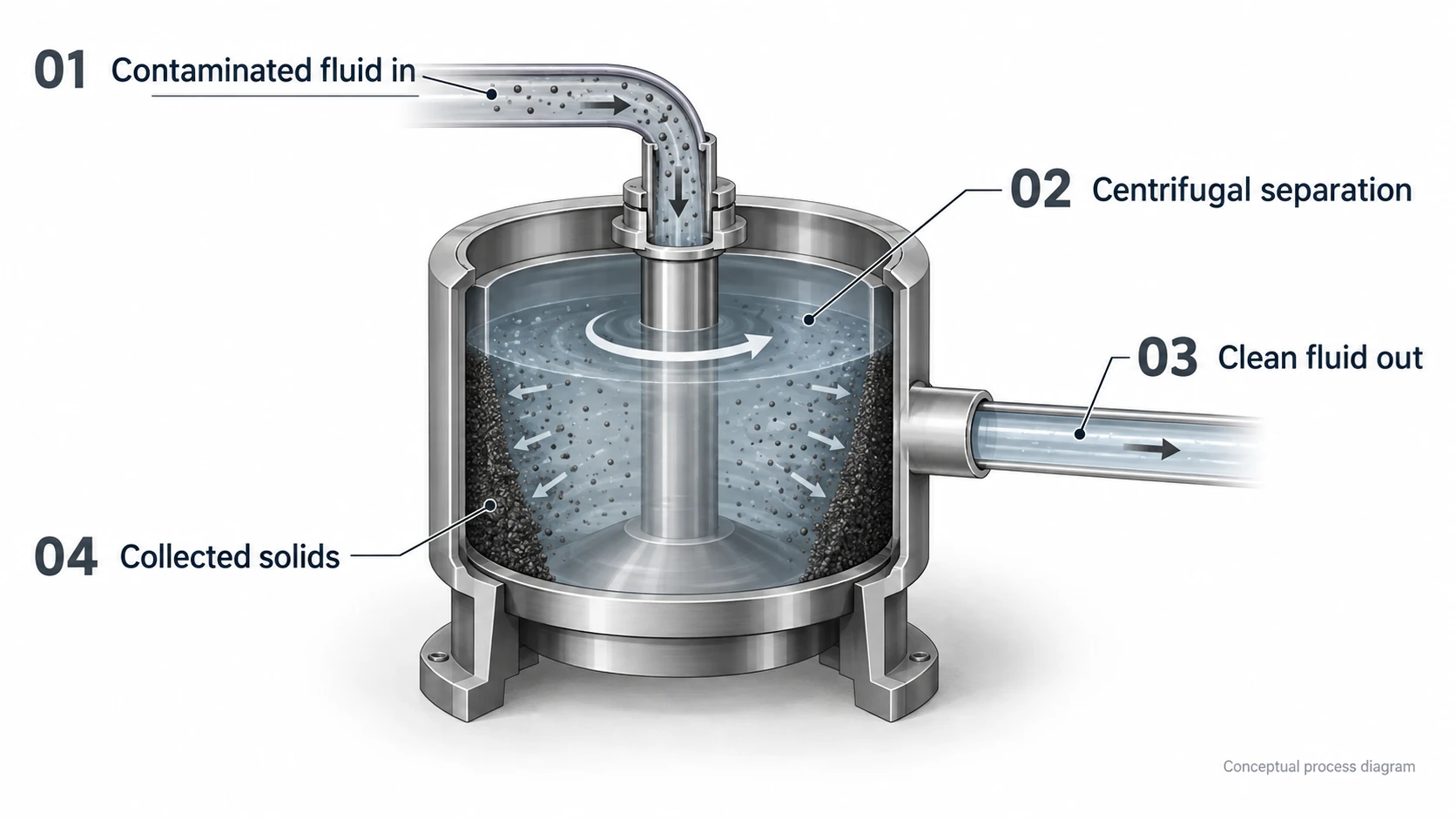
01Fluid InPump coolant from the machine sump or central tank.02AccelerateRotation generates force many times stronger than gravity.03SeparateDenser solids migrate toward the bowl wall.04ReturnSeparated fluid returns to the production circuit.
Conceptual coolant centrifuge diagram showing contaminated fluid inlet, centrifugal separation, clean fluid outlet and collected solids

Performance depends on G-force, residence time, flow rate, viscosity, particle density and particle size. Higher flow is not automatically better when the target is very fine solids.

04 · Choose the discharge method

Automatic or Manual Sludge Discharge?

The discharge method is a labour and process decision, not simply a performance ranking. Selection should reflect how quickly solids accumulate, how often operators can inspect the bowl, whether the line can pause and how much variation occurs between shifts. A well-sized manual unit may suit an intermittent process, while continuous production usually benefits from controlled automatic discharge.

CONTINUOUS PRODUCTION

Automatic Sludge Discharge

Designed for repeated solids generation, multiple shifts and applications where routine manual bowl cleaning would interrupt production.

  • Controlled discharge cycle
  • Lower routine operator intervention
  • VC-600 / 800 / 1500 / 2000
Series page in development
BATCH OR INTERVAL CLEANING

Manual Discharge

Suitable for batch cleaning, dedicated machines or lower solids loading where a planned manual cleaning interval is acceptable.
  • Lower initial equipment complexity
  • Operator removes collected solids
  • VC-30 series
Series page in development
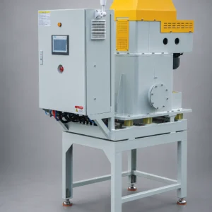
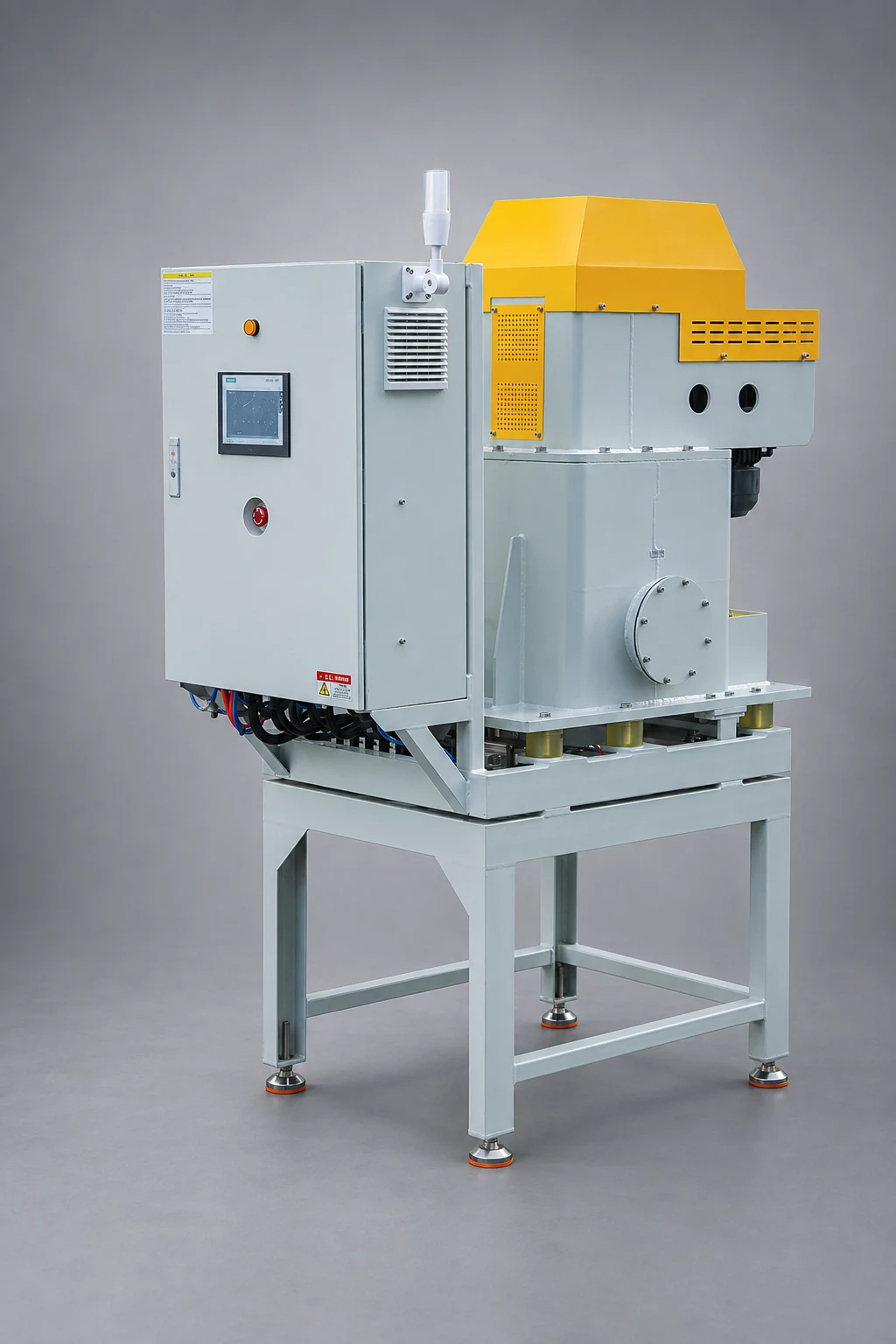
VC-1500 automatic sludge discharge coolant centrifuge
VC-1500 · Automatic sludge discharge centrifuge
05 · Compare models

VC Coolant Centrifuge Range

Compare flow, G-force and solids capacity together. The largest flow number is not automatically the best choice for fine solids. Begin with the required sump turnover, then check whether the available residence time and centrifugal force match the contaminant. Solids capacity matters when loading is heavy because it determines how frequently collected material must be discharged.

ModelMax. Rated FlowMax. G-ForceSolids CapacitySelection Direction
VC-60060 L/min6,500 G2 LHighest G-force; fine dense solidsView Model →
VC-80080 L/min2,800 G3.2 LMid-range flowView Model →
VC-1500150 L/min1,860 G8 LMultiple machines; central sumpView Model →
VC-2000200 L/min1,700 G20 LHigh solids loadingView Model →

Rated flow is not a universal process guarantee. Final sizing considers viscosity, temperature, contaminant density, required turnover, pipe routing and pump duty.

06 · Application routes

Where Coolant Centrifuges Are Used

MACHINING

CNC & Grinding

Fine chips, swarf and dense grinding contamination in dedicated or shared sumps.

Detailed page in development
WIRE

Wire & Cable

Metal fines carried by wire drawing lubricant and drawing emulsion.

Detailed page in development
STEEL

Tube & Rolling Mill

Mill scale, drawing contamination and suspended metallic solids.

Detailed page in development

Multiple-machine installations may require a central sump, circulation pump, coarse protection and controls. The centrifuge is one treatment stage within the complete fluid circuit.

Application review should also consider fluid compatibility, operating temperature, particle density and the volume of solids generated during peak production. Samples or site data help distinguish a separation problem from a chemistry-control problem and prevent selection by flow rate alone.

07 · Verify the result

Measure What Changes After Separation

The first visible output is the separated solids stream: metal sludge is removed from circulation instead of remaining in the sump. The operating benefit comes from preventing the same particles from returning through the production process.

01Filter-media consumption02Sump-cleaning frequency03Fluid-change interval04Nozzle blockage and maintenance

Results must be tied to a real baseline. Record media use, maintenance intervals, coolant condition and solids volume before installation, then compare the same measures after commissioning. We do not apply one savings number to every plant.
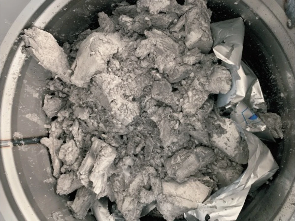
Grey collected solid material in a round container
Get a model recommendation

Size the Centrifuge Around Your Process

Send your fluid type, contamination, temperature, sump volume, required flow, number of machines and available voltage. We will compare G-force, flow and solids capacity for your application.

Request Selection Support →
Fluid and concentrationContaminant and particle typeOperating temperatureSump volume and machine countRequired circulation flow380V/50Hz, 400V/50Hz or 480V/60Hz
Scroll to Top