
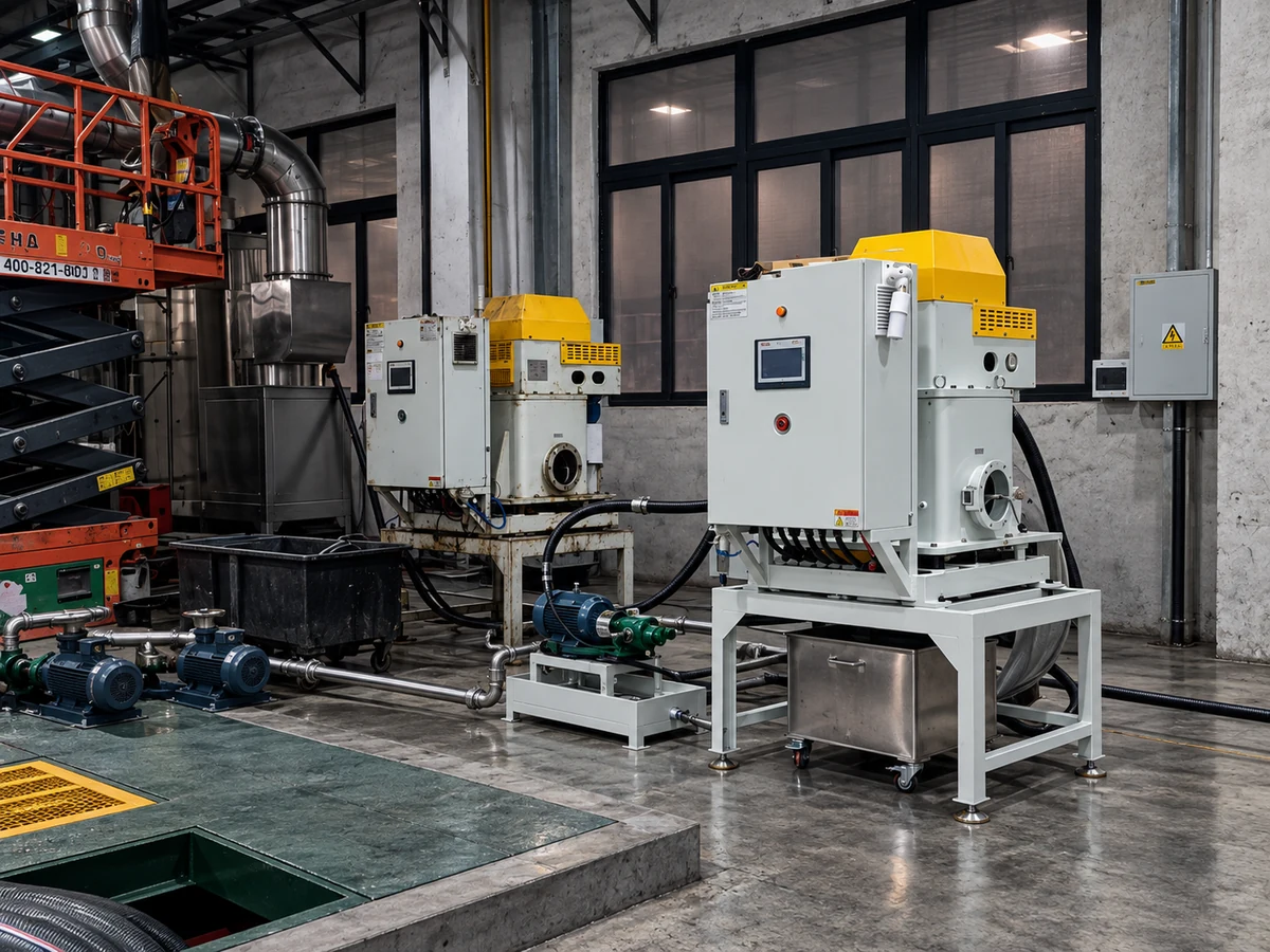
A small central loop for cold heading oil filtration collects dirty return oil from a compatible group of machines, removes suspended contamination and sends treated oil back through a defined supply route. The practical design task is to keep contaminated return oil moving toward treatment while maintaining the level and supply each forming machine needs.
A compatible group can share oil collection and treatment while retaining a clear branch for each machine. The broader cold heading oil filtration application explains the solids duty; this guide concentrates on how the shared circuit behaves during production, machine stops and tank service.
What a cold heading oil filtration loop must solve
Separate the reasons for considering a central loop. A plant may want to collect suspended fines, reduce manual handling at individual machines, improve access for maintenance, or consolidate fluid checks. These are different objectives. A separator can address a suitable suspended-solid fraction without correcting every cause of lubricant deterioration.
Map where contamination enters. Forming fines, incoming surface material and deposits already in the tank may follow different paths. If a deposit is described as phosphate residue, confirm its identity before using that description to select treatment. The phosphate residue discussion concerns a specific contamination question, rather than a label for every dark sludge.
List the connected machines and whether they use the same oil specification. Combining incompatible formulations creates a fluid-management problem that cannot be corrected simply by adding a centrifuge. Include top-up oil and fluid carried from adjacent operations in that review.
Draw the collection and return routes
Follow each machine drain to the shared collection point. Continuous returns, transfer-pump batches and shutdown drain-back arrive at different times. The treatment intake should reach that dirty inventory after coarse protection rather than drawing from a convenient clean compartment.
Then draw the clean return and process supply. A return close to the treatment suction can repeatedly circulate the same liquid while leaving other parts of the inventory poorly exchanged. Include tank compartments, levels and any routes that bypass the treatment stage.
A central connection does not establish full-flow filtration. A side stream treats part of a shared inventory over time; a full-flow arrangement places treatment in a defined supply path. The distinction affects sampling and acceptance. Discuss the complete centrifugal coolant filtration system rather than treating the separator as an isolated purchase.
Define operating states before equipment selection
The same loop has to work with all machines running, with one branch stopped and at a plant shutdown. During production, returns and transfer pumps maintain the intended compartment levels. When one machine stops, its branch follows the approved isolation arrangement. At shutdown, oil held in lines and enclosures can drain back, so the reservoir needs receiving space and the specified level controls for that transition.
The cleaning flow is a separate question from the oil supplied to the forming machines. Vimfun's VC-600 manufacturer specification gives a recommended treatment flow of 40 L/min and a maximum of 60 L/min. Those figures belong to the cleaner, not the combined lubrication demand of the cell. Working viscosity, particle load and available running time determine the proposed treatment point.
In the rotating bowl, denser forming fines migrate toward the wall while the treated oil follows its outlet path back to the tank. Collected material goes to a sludge receiver through the supplied discharge arrangement. A stable liquid flow therefore still needs space for receiver changes and access for inspection. Resolve those movements before fixed pipes make relocation difficult.
Agree a comparison that the plant can maintain
Use repeatable sample points on the dirty feed and treated stream. For a shared inventory, add a point that represents the oil delivered back to the forming machines. Label samples with location, operating state and relevant additions so that a cleaner sample is not accidentally compared with a more diluted one.
Oil additions and drains must remain visible in the record. If a large top-up occurs between samples, the change cannot be attributed entirely to treatment. Likewise, sludge-container weight includes retained oil unless a different mass basis is established.
Swipe horizontally to compare all columns.
| Objective | Practical record | Decision supported |
|---|---|---|
| Reduce suspended contamination | Comparable fluid analysis at named points | Whether the targeted solids measure changes |
| Improve tank housekeeping | Deposit observations and cleaning work records | Pickup position and access for settled material |
| Reduce oil replacement | Additions, drains, change triggers and production | Whether the change interval and total consumption improve |
| Simplify operator work | Time and handling observations | Receiver location and the routine service arrangement |
When a good separator-outlet sample coincides with a dirty machine-supply sample, examine tank exchange and continuing contamination input. When the outlet itself remains heavily loaded, examine the feed, viscosity and chosen treatment point. These observations direct different changes instead of a general instruction to increase loop flow.
Commission the shared arrangement in stages
Before a production trial, agree the supplier's installation requirements, responsible personnel and inspection sequence. First establish that the supplied equipment and connected circuit can operate as intended. Then assess the fluid result using the agreed sampling plan. A visible start-up is not an oil-life test.
Observe transfer, return and collection behaviour at the permitted operating states. Record which machines were connected during each observation. If a problem appears only during a shift change or a shutdown, preserve that context instead of averaging it out of the report.
Document changes to collection positions or returns. Otherwise, later measurements may compare two different circuits while appearing to compare separator performance alone. Keep the current layout with the machine instructions so that the next maintenance team can identify each connection.
Decide whether the arrangement is worth expanding
Evaluate the small loop before connecting more machines. A larger shared inventory changes the operating context, even when the same oil formulation is used. Additional drains, levels and solids loads should be reviewed against the approved treatment duty.
Include treatment maintenance, retained oil in sludge, transfer equipment and operator work in the cost discussion. A theoretical reduction in fluid purchase is incomplete if another part of the arrangement creates unrecorded losses or handling time.
To discuss a central-loop arrangement with Vimfun, send a circuit sketch, connected-machine list, oil specification, contamination information and the maintenance objective. Those inputs help us separate the treatment duty from the supply and collection tasks that belong to the shared circuit.
Frequently asked questions
Does a central loop mean all supply passes through the cleaner?
Only a circuit arranged for full-flow treatment does that. In a side stream, map the untreated supply and treated return separately and use the machine-supply sample to assess the shared inventory.
Can different cold heading oils share a system?
A shared inventory needs compatible formulations and process requirements. Keep incompatible grades in separate circuits and review top-up and carryover routes before connecting machines.
What does visible sludge discharge show?
It shows collected material leaving the unit. To assess oil use, record the collection period, retained oil, top-ups, drains and the condition that triggers an oil change.
What should be supplied for a central-loop discussion?
Send a circuit sketch, connected-machine list, oil identity, operating conditions and the maintenance problem. Those inputs help Vimfun assess treatment and circulation together.