
Application · B16

Ceramic Grinding Coolant Filtration

Assess alumina, zirconia and mixed grinding fines with a sample-led separation plan for your ceramic process.

Assess Your Ceramic Grinding Fluid

Ceramic Materials Create Different Filtration Duties

Ceramic grinding coolant filtration starts with the workpiece material and the operation. Alumina, zirconia and other technical ceramics can generate fine residue during grinding, but their particle populations and process requirements are not identical. Wheel wear and dressing material can add further components to the liquid. A single description such as ceramic sludge is therefore insufficient for equipment selection.

Distinguish grinding a sintered component from machining a green body or running an intentional abrasive slurry. Binders and other process ingredients may change both the separation behaviour and the meaning of a successful result. Material that is unwanted in one circuit may be a useful constituent in another. Record the fluid product and any deliberately suspended components.

The target may be lower recirculating solids, fewer deposits, more stable coolant delivery or a production-quality concern. Define that target before comparing machines. Centrifugal separation should be assessed as one part of the fluid circuit, not as a blanket guarantee of better dimensions or surface finish.
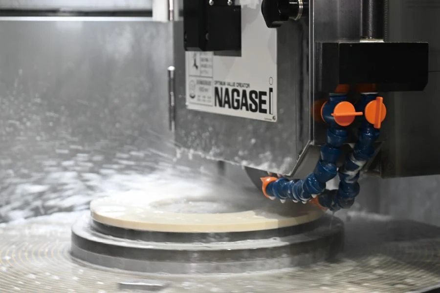
Grinding machine applying coolant to a circular workpiece

Follow the Contamination through the Circuit

Fine ceramic residue can travel beyond the initial collection point and remain available to return to the grinding zone. Other material settles in the sump, pipework or low-flow corners. An outlet sample taken from one accessible point may not describe the material that accumulates elsewhere during a production run.

Map the machine return, coarse collection stage, sump, feed pump and coolant delivery. Note whether several ceramic grades share the same circuit and whether the plant changes fluids between jobs. This identifies where a treatment stream can be taken and where cross-contamination or poorly mixed regions could undermine a trial.

If the main concern is a surface defect, examine the defect with the production team. Wheel condition, dressing, feed, fixture stability and coolant delivery must remain part of the investigation. Cleaner fluid may address a contamination-related contribution, but it does not remove the need to control these other variables.

Evaluate Centrifugal Separation with the Actual Mixture

Suitable dense particles can be concentrated in a rotating separator while the clarified liquid returns to the process. This provides a route to solids control without disposable paper in the centrifugal stage. Actual performance depends on the particle distribution, liquid viscosity, treatment flow and the way material collects and discharges.

Do not assume that a result on alumina automatically applies to zirconia, or that all fines from one material will separate equally. Mixed residue, fine dispersions and soft binder-containing material may behave differently. Test the liquid from the actual grinding duty and record the conditions that produced it.

A solids separator does not restore depleted coolant chemistry or guarantee removal of dissolved contaminants. It may also be unsuitable for retaining a required working abrasive while removing another particle population. When selective recovery is the objective, the trial must measure both the unwanted residue and the valuable component.

Use a Trial Plan That Production Can Evaluate

From sample to process decision
QuestionInformation to recordDecision supported
What enters the fluid?Ceramic grade, wheel and dressing residue, bindersWhether centrifugal separation is a candidate
What must remain?Coolant chemistry and any useful abrasiveWhether clarification damages the process formulation
What leaves the separator?Outlet condition and collected-solids consistencyFurther treatment and handling requirements
What changes in production?Agreed surface or delivery measurementsWhether the benefit addresses the original problem

Set the acceptance method before inspecting a before-and-after photograph. A change in colour or visible sediment is not a particle-size analysis. Where the application has tight cleanliness requirements, agree how the samples will be prepared and measured, and ensure that the method is appropriate for the ceramic fluid rather than borrowed without review from another industry.

Choose Flow and Discharge Together

Treatment flow should reflect solids generation and the fluid volume to be maintained. A central installation also needs enough collection and discharge capacity to handle sustained loading. Selecting only the largest flow number can overlook the interval between solids-removal events and the practical demands placed on operators.

El VC-600 offers a 6,500 G, 60 L/min rated reference for high-force assessment. The VC-1500 offers 150 L/min rated flow and 8 L solids capacity for a different duty range. These figures identify the equipment; they are not a guaranteed ceramic-slurry processing result.

Review automatic sludge discharge where the expected loading makes repeated manual removal impractical. The consistency of collected ceramic residue should be observed during the trial. Automatic discharge still requires collection, inspection and maintenance, and should not be described as maintenance-free operation.

Prevent Cross-Contamination during Integration

A bypass loop should receive representative dirty fluid and return treated fluid where it can rejoin the circulating inventory effectively. Keep suction and return placement from creating a short path that repeatedly treats the same liquid while leaving the rest of the sump poorly served. Include the normal operating levels in the layout review.

Where grades must remain segregated, identify whether the separator is dedicated or shared. A shared unit needs a defined changeover procedure and an agreed way to avoid transferring residue from one ceramic to another. Hose identification, collection containers and access for cleaning should be resolved before installation, not added as an informal operator workaround.

El central coolant filtration system guide provides a starting layout framework. The correct arrangement still depends on the ceramic process, fluid compatibility and the plant's quality controls. Connections alone do not establish that two machines should share treated coolant.

IMAGE SLOT · 4:3Ceramic grinding coolant and collected fine residue for laboratory assessment
File: ceramic-coolant-alumina-zirconia-fines.webp

Review the Result beyond the First Sample

A short trial can establish whether useful separation occurs at a defined setting. It cannot by itself prove a longer sump-cleaning interval or sustained surface-quality improvement. Those outcomes need a production record covering the relevant shifts, loading and product mix.

Record the change in solids handling as well as the liquid result. Moving contamination out of the sump is helpful only when the collection route is workable and maintained. Note operator time, container changes and any cleaning difficulties without converting an early trial into an unsupported cost-saving claim.

For related processes, see quartz grinding coolant filtration y filtración de refrigerante de rectificado. The shared principle is sample-led selection; the ceramic grade and process requirements determine the final recommendation.

Assess Your Ceramic Grinding Fluid

Send the ceramic grade, grinding method, coolant specification, sump size and contamination concern. A representative sample helps define the separation trial.

Send Application Details
Scroll al inicio