
Application · B18

Metalworking Fluid Filtration

Separate chips and fines from the wider fluid-management problem. Build a treatment system around the contamination your machines actually generate.

Plan Your MWF Treatment

Filtration Is One Part of Fluid Management

Metalworking fluid filtration controls unwanted material circulating in machine-tool fluids. It may involve coarse chip collection, magnetic separation, media filtration, centrifugal separation or a combination. The correct choice depends on the fluid, workpiece material, particle population and outlet requirement, not on a claim that one technology is universally best.

Neat oils and water-mix fluids present different management needs. Water-mix fluids also require control of their working condition; removing solids alone does not resolve concentration, water quality or microbiological problems. Neat oils need their own checks for contamination and chemical condition. A filtration proposal should identify which problem it addresses and which controls remain with the plant and fluid supplier.

Start by separating three questions: what enters the liquid, what must be removed, and what must remain suitable for use. This prevents equipment intended for suspended particles from being expected to restore an exhausted formulation or remove every type of unwanted liquid.
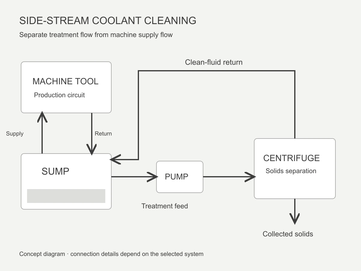
Concept diagram of a coolant sump bypass loop with pump, centrifuge and clean-fluid return

Classify the Contamination before Comparing Equipment

Bulk chips, fine metallic debris, grinding residue, free tramp oil and dissolved contamination are different treatment duties. Some machines generate several at once. A line producing long chips needs effective coarse handling even if its main maintenance complaint is sludge; a grinder may place more emphasis on suspended fines.

Record contamination by source rather than using only the label dirty coolant. Include the workpiece material, wheel or tool contribution, incoming coatings and any leaks from machine lubrication systems. A representative sample and a simple circuit sketch are often more informative than a photograph of a dark sump.

fines removal guide covers the suspended-solid fraction in more detail. The broader task here is to put that step in the right place within the complete fluid circuit and leave unrelated fluid-treatment duties with an appropriate method.

Compare Treatment Stages by Their Actual Job

Possible stages in an MWF treatment circuit
StageUseful dutyImportant limit
Conveyor or screenBulk chips and coarse debrisFine suspended material can remain
Magnetic separationSuitable ferromagnetic contaminationNot a general solution for nonmagnetic particles
Paper or bag filtrationRetention through selected mediaMedia choice, loading and replacement require attention
Centrifugal separationSuitable dense suspended solidsPerformance depends on fluid and particle conditions
Free-oil removalSeparated unwanted oil at the surface or in a compatible streamNot equivalent to separating a stable emulsion

Stages can complement one another. Coarse removal protects downstream equipment, while a fine stage reduces the material that continues to circulate. Compare actual operating requirements in centrifuge versus paper band filter, including waste handling and operator work rather than consumable cost alone.

Where a Coolant Centrifuge Fits

A coolant centrifuge concentrates suitable suspended particles under centrifugal force and returns clarified liquid. Its role is most useful when the troublesome solids can separate from the fluid at a practical flow. No disposable filter paper is consumed by the centrifugal stage, but service, energy and solids handling remain part of the operating cost.

coolant centrifuge category guide explains the equipment family. A sample trial should establish the operating point for the actual fluid. A nominal rated flow is not an absolute filtration grade, and increasing flow does not guarantee the same outlet result with smaller particles or a more viscous liquid.

Do not use a successful solids trial as evidence that the fluid is biologically controlled, chemically restored or ready for unrestricted reuse. Agree the remaining fluid-condition checks with the supplier. The cutting-fluid life guide covers the broader maintenance work that continues alongside separation.

Dedicated Sump or Central System?

A dedicated arrangement isolates one process and can make a trial easier to interpret. The feed and return can be matched to a known machine, fluid product and solids source. It may be appropriate where contamination differs between production cells or where a central connection would create unnecessary pipework and changeover complexity.

A shared system serves a larger inventory and may offer a more organised maintenance point. It also combines the operating behaviour of several machines. Fluid compatibility, production peaks, return routing and contamination transfer must be considered before connecting previously separate sumps.

使用する central-system planning page to develop the layout. Record both the main circulation and the proposed treatment stream. A bypass separator usually addresses the contamination balance over time; it should not be sized solely by copying the highest machine-pump rating in the workshop.

Define Cleanliness in a Way the Process Can Use

An outlet requirement should identify both the measurement and the sampling method. A visual sample comparison can document appearance, but it does not establish a particle count, a surface-quality guarantee or a fluid-life extension. If a customer requires a cleanliness code, confirm that the method is appropriate for the particular fluid and particle mixture.

Choose representative operating conditions for the trial. A quiet shift with a freshly cleaned sump may not reveal the peak solids burden. Record machine loading, fluid temperature, test flow and the collection cycle so that the result can be related to normal production rather than treated as a stand-alone photograph.
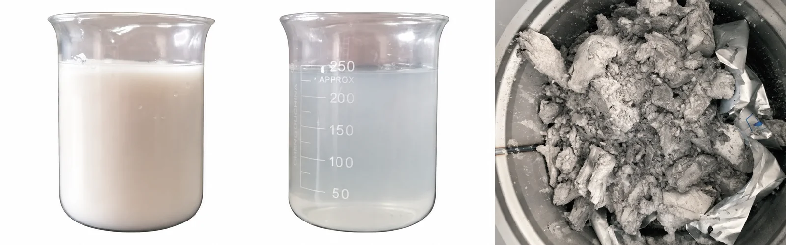
Catalogue examples of untreated coolant, clarified liquid and separated solids
Liquid and separated-solids sample examples.

Measure Maintenance and Production Outcomes Separately

Keep a record of sump cleaning, filter-media use, collection-container handling and service work before changing the system. After installation, compare the same activities over an appropriate operating period. A reduction in one task may be offset by another, so a useful evaluation follows the complete routine.

For equipment direction, the VC-600 provides a high-force option to assess, while the VC-1500 offers a different rated-flow and solids-capacity range. Select between them only after fluid, particles and load have been reviewed.

The outcome should be a defined treatment duty, a practical maintenance plan and evidence that the selected stage addresses the original concern. Filtration can support fluid cleanliness, but sustainable MWF management still depends on correct fluid use, machine housekeeping and routine condition control.

For maintenance planning, use the sump cleaning guide. If the immediate concern is odour rather than measured solids, start with why coolant smells and the appropriate fluid-condition investigation.

Plan Your MWF Treatment

Share your machining processes, fluid products, sump volumes, contamination types and maintenance records. We will review where solids separation fits in the circuit.

Send Application Details
上部へスクロール