
Trolley and equipment access
The trolley-mounted arrangement is designed for a movable installation. Check door widths, floor conditions, access routes and the final equipment dimensions before selecting the unit.
A trolley-mounted manual-discharge centrifuge for moving between suitable industrial fluid circuits. Rated processing flow is 960 L/h, with 4.5 L solids capacity.
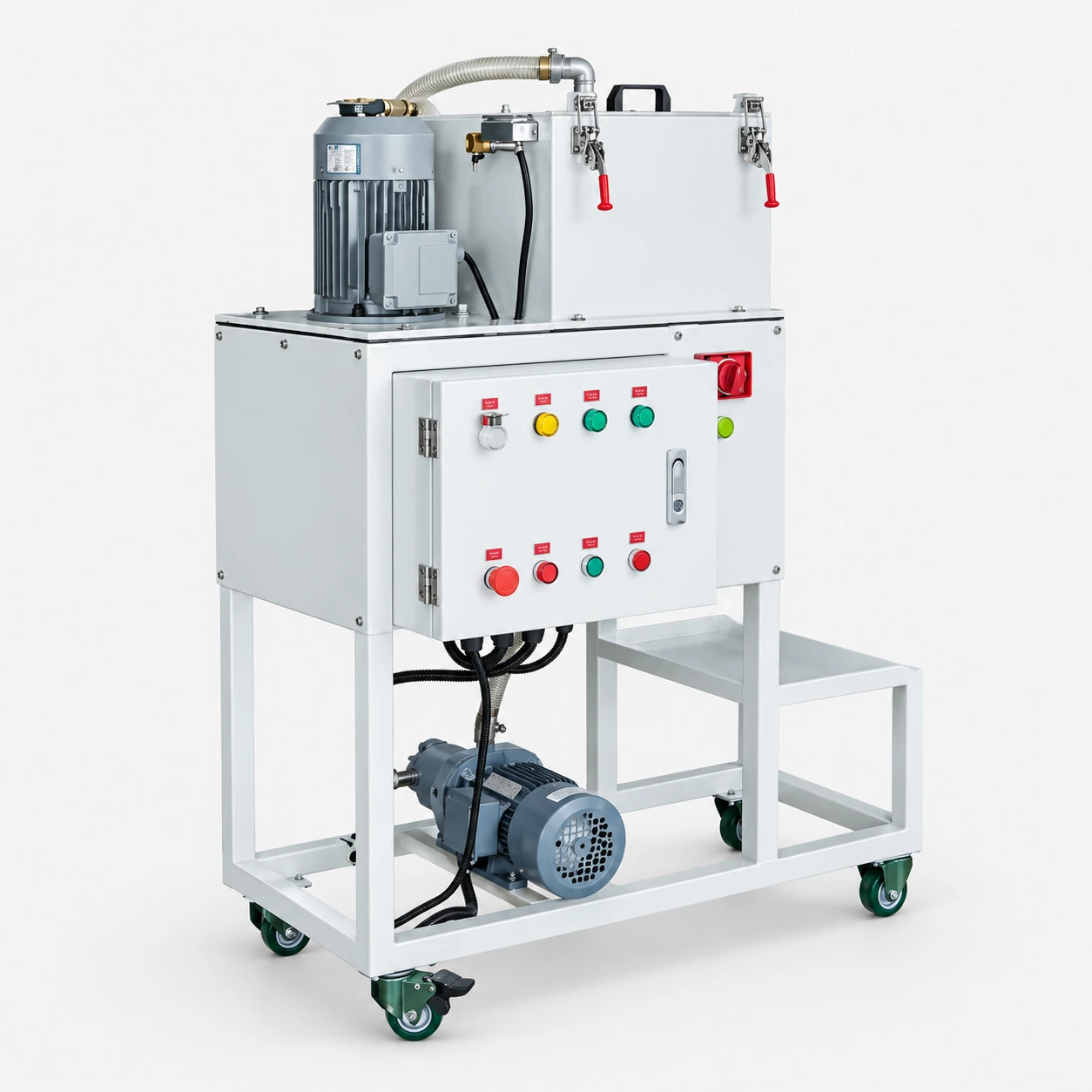
The VC-30P combines the manual-discharge separation configuration with a wheeled trolley layout. Consider it where treatment is arranged around individual sumps or a changing production layout. Movement does not eliminate the need to disconnect, secure and reconnect the equipment using the approved operating procedure.
The trolley-mounted arrangement is designed for a movable installation. Check door widths, floor conditions, access routes and the final equipment dimensions before selecting the unit.
Review the specifications alongside your process conditions and installation requirements. The quotation should confirm the configuration, connections and required documentation.
Review the standard specifications below. Dimensions are listed as length × width × height. Confirm the final configuration and installation dimensions in the quotation and approved drawing before ordering.
| Discharge mode | Manual solids removal |
|---|---|
| Processing flow | 960 L/h |
| Total power | 2.75 kW |
| Solids capacity | 4.5 L |
| Operating temperature | 0–80°C |
| Dimensions (L × W × H) | 1,100 × 720 × 1,500 mm |
| Weight | 200 kg |
| Reference electrical supply | Three-phase 380 V |
| Inlet / outlet | DN26 / DN65 |
| Catalog fluid-volume reference | Within 1.5 tonnes; application review required |
Provide your site voltage and frequency so electrical compatibility can be confirmed before ordering.
Feed the contaminated fluid to the centrifugal separation stage, return clarified liquid to the circuit and retain separated solids for manual removal. Manual discharge means the operator must plan a solids-removal routine; this is a different arrangement from the automatic-discharge VC models.
Check feed and return positions, piping and the existing sump arrangement. Avoid assuming that the processing-flow rating establishes the time needed to reach a particular fluid-quality target.
The 4.5 L solids capacity describes the collection capacity, not a fixed time between cleaning operations. Solids generation and the condition of the deposit affect the required routine.
Stop and isolate the machine before opening the solids chamber. Follow the shutdown and cleaning procedure in the operating manual.
Review the fluid volume, contamination and required treatment schedule for each sump. Treating several sumps in sequence differs from supplying continuous filtration to all machines at once.
The wheeled arrangement does not establish safe movement while running or while carrying hot fluid. The 200 kg stated machine weight must be considered in site handling arrangements.
Provide representative process conditions and the treatment result you need so the configuration can be assessed for your application.
The reference VC-30P configuration is 1,100 × 720 × 1,500 mm and weighs 200 kg. Provide the narrowest access width, floor conditions and intended parking location. Confirm the final trolley arrangement and handling instructions before planning movement between machines.
Identify feed and return connections for each sump, the available power supply and a practical treatment schedule. Disconnect and secure the unit according to the supplied procedure before moving it. Trolley mounting does not establish permission to move the unit while running or while it contains hot fluid.
| Configuration | VC-30T | VC-30P | VC-30C |
|---|---|---|---|
| Main selection point | Temperature | Trolley layout | Custom layout |
| Temperature | 0–110°C | 0–80°C | 0–80°C |
| Processing flow | 960 L/h | 960 L/h | 960 L/h |
| Solids capacity | 4.5 L | 4.5 L | 4.5 L |
| Weight | 80 kg | 200 kg | 125 kg reference |
All three models have a rated processing flow of 960 L/h and 4.5 L solids capacity. Select around operating temperature and installation layout. For rotational speed or G-force requirements, request confirmation for the selected manual-discharge model.
Provide an installation sketch, connection positions, available floor space and service clearances. Confirm the final drawing rather than relying on the photograph alone.
State the electrical supply and operating conditions. Confirm the control interface and commissioning requirements for the quoted configuration.
Request the operating manual and maintenance instructions for the actual build. Agree the inspection routine and any site-specific requirements before commissioning.
The AI-enhanced image illustrates the equipment arrangement. Confirm the delivered configuration in the quotation and model-specific drawing.
Specify your site voltage and frequency. Confirm electrical compatibility and any required adaptation in the quotation.
Suitability depends on your fluid or vapour composition, contamination and operating conditions. Agree the treatment target and any required sample testing before ordering.
Provide process composition, operating temperature, expected loading, required treatment schedule, installation sketch and utilities. State the result you need so the configuration can be assessed against it.
Request a review of the proposed VC-30P configuration. Include the operating conditions and a sketch of the intended connection layout so the equipment and documentation requirements can be checked together.
Request a VC-30P Review