
Grinding Coolant Nozzle Blockage: Diagnose the Restriction Before Adding Filtration
In this article
Grinding coolant nozzle blockage is one possible explanation for a weak or uneven coolant jet, but it is not the only one. A supply problem, loaded strainer, changed valve position or damaged nozzle can produce similar symptoms. Repeatedly cleaning the nozzle without checking the upstream system may leave the original fault in place.
Start by locating the restriction and identifying what was removed. This guide concerns solids-related investigation in grinding coolant circuits. Machine operating limits, nozzle setup and maintenance work must follow the grinder manufacturer's instructions; a general filtration guide cannot specify the correct jet or pressure for every grinding process.
Confirm whether the nozzle is actually obstructed
Record the observed change before dismantling anything: one nozzle affected or several, a gradual reduction or a sudden loss, and whether the problem appears after startup or during a particular operation. These distinctions help the maintenance team decide where to inspect first.
Use installed instrumentation and approved checks to review the supply condition. A pressure reading at one point does not establish adequate flow at the nozzle. Equally, a poor-looking jet does not establish that particles are lodged inside it. Interpret the available readings against the machine's specified arrangement.
Isolate equipment and release stored energy through the site's maintenance procedure before opening components. Do not try to clear a restriction on a running grinder or probe a pressurized nozzle. Preserve the removed material when its identity may explain the recurring problem.
Identify what is caught at the restriction
Place material removed from the nozzle or strainer in a labelled container and record its source. Is it recognizably long debris, fine particulate sludge, fragments of another component or an unidentified deposit? Photographs can document shape, but composition may require closer examination or laboratory analysis.
Do not call every blockage grinding fines. Mixed debris may enter from a maintenance activity, damaged component or another part of a shared coolant system. If contamination reappears soon after cleaning, compare the newly collected material with the first sample rather than assuming the mechanism is unchanged.
Avoid assigning a particle-size requirement from a photograph. The relevant information includes the obstruction geometry, the material being trapped and the machine supplier's coolant cleanliness requirements. Those inputs define what the upstream treatment must address.
Inspect the last treatment stage before the nozzle
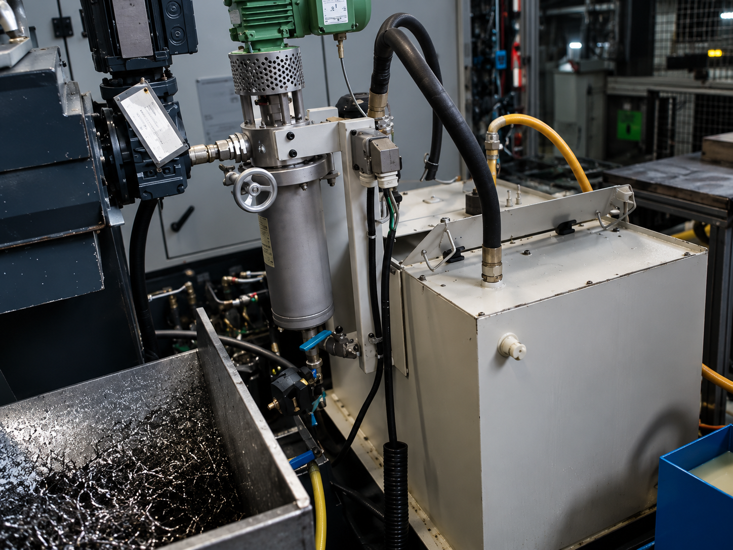
Trace the supply from the tank through pumps, screens, filters and distribution pipework. Identify the final protective element before the nozzle. Check its condition and whether there is an operating path around it, using the manufacturer's inspection procedure.
A damaged or incorrectly installed element may allow larger material through even when the system has substantial treatment capacity elsewhere. Conversely, an intact element that loads rapidly may indicate a feed problem or maintenance issue rather than a need to alter the nozzle itself.
Retain the distinction between tank cleanup and final supply protection. A bypass treatment loop can reduce circulating contamination over time, but it does not necessarily intercept every particle on its way to the nozzle. The actual arrangement determines that protection.

Look for contamination introduced downstream
If material is found at the nozzle despite suitable upstream protection, inspect the section between the protective stage and the nozzle. Maintenance debris or deterioration within that section should be considered rather than automatically blaming the sump.
Review recent hose replacements, component work and cleaning activities. Record the timing of the blockage relative to those changes. A problem that began after an intervention warrants inspection of the modified section before an equipment upgrade is specified.
Do not enlarge a nozzle opening as an informal fix. Changing its geometry may change coolant delivery to the grinding zone. Any change should be reviewed against the process requirements, not judged only by whether the opening is less likely to obstruct.
Decide what a separation stage can contribute
Where suspended solids in the circulating coolant are the confirmed source, a separation trial can help evaluate an upstream treatment option. Supply the actual coolant and solids, including information about abrasive material, workpiece material and existing treatment. For carbide tool grinding, use the sampling points in the tool grinder coolant separation guide to compare the separator inlet and return during the same run.
A centrifuge is not a universal barrier with a fixed pore opening. Its result depends on the feed and operating conditions. A satisfactory sample result therefore needs to be connected to the proposed installation and to any remaining requirement for protective screening or filtration.
Ask the test provider what was measured in the treated liquid and what remained. Do not use a clearer bottle as proof that every particle capable of blocking a particular nozzle has been removed. The test objective should reflect the obstruction mechanism identified during maintenance.
Test the correction against a defined baseline
Select a repeatable observation, such as interventions on the same nozzle or loading of a specified strainer over a recorded production period. Keep the nozzle configuration, measurement method and production details in the comparison record.
If several changes are made together, explain that the result reflects the combined intervention. Cleaning a tank, replacing a damaged element and installing a separator at the same time does not isolate the contribution of each action. That does not invalidate the improvement, but it limits the claim you can make about its cause.
Also check that the original delivery requirement is being met. A nozzle that stays clear is not a successful outcome if the coolant supply no longer satisfies the grinding process. Review the result with the machine and process teams, not only the treatment supplier.
Prepare the information needed for a useful recommendation
For the maintenance record, separate these findings instead of writing only "nozzle cleaned":
- The affected outlet and the observed delivery problem before intervention.
- The component opened and the location of any actual obstruction.
- The appearance and retained sample identification of removed material.
- The approved corrective action and the subsequent delivery check.
If nothing was found inside the nozzle, record that too. A negative finding is useful evidence for moving the investigation upstream rather than repeatedly treating an unconfirmed blockage.
Provide the grinder type, coolant product, workpiece and abrasive information, the affected nozzle arrangement and a sketch of the supply circuit. Add photographs of the removed obstruction and any available flow or pressure records, clearly stating where they were measured.
The grinding coolant filtration guide provides the broader solids-control context. For recurring nozzle blockage, the next step is a targeted review of the restriction and protection path. That approach avoids buying treatment equipment for a problem that actually originates in a hose, component or supply setting.
Discuss Your Grinding Coolant
Share the coolant details, obstruction observations and supply circuit.
Request a Technical Review →