
Automatic response to load
Operation adjusts automatically according to load. Confirm the control arrangement, allowable inlet conditions and commissioning requirements for the selected configuration.
Solvent-vapour collection and recovery configurations with rated airflow ratings of 40, 80 and 100 m³/h. The reference configuration includes automatic load adjustment and direct-expansion cooling.
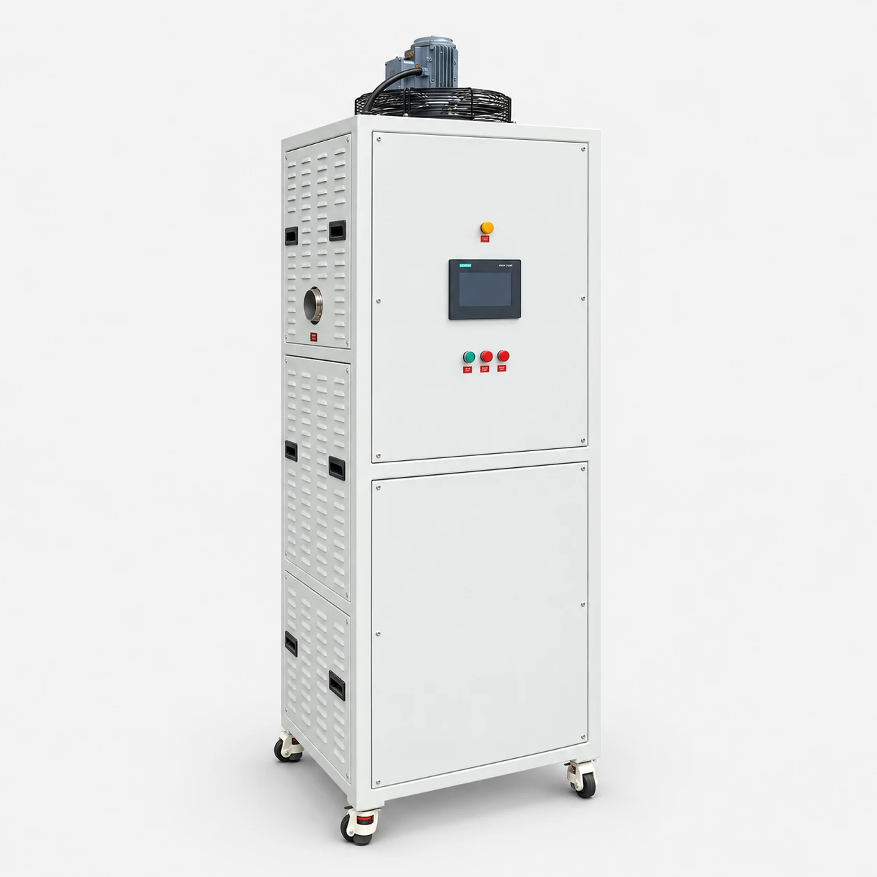
Compare VR-40, VR-80 and VR-100 by airflow, collection-tank volume and installation requirements. Airflow is separate from solvent recovery rate; assess the recovered quantity and required outlet concentration for the actual vapour stream.
Operation adjusts automatically according to load. Confirm the control arrangement, allowable inlet conditions and commissioning requirements for the selected configuration.
Review the specifications alongside your process conditions and installation requirements. The quotation should confirm the configuration, connections and required documentation.
Review the standard specifications below. Dimensions are listed as length × width × height. Confirm the final configuration and installation dimensions in the quotation and approved drawing before ordering.
| Model | VR-40 | VR-80 | VR-100 |
|---|---|---|---|
| Source model | FY-BZQ-40 | FY-BZQ-80 | FY-BZQ-100 |
| Airflow | 40 m³/h | 80 m³/h | 100 m³/h |
| Collection tank | 1 L | 2 L | 2 L |
| Total power | 0.85 kW | 1.7 kW | 2.4 kW |
| Reference supply | 220 / 380 V | 220 / 380 V | 220 / 380 V |
| Dimensions (L × W × H), mm | 623 × 487 × 805 | 580 × 580 × 1,600 | 2,000 × 1,500 × 2,119 |
| Cooling system | Direct expansion | Direct expansion | Direct expansion |
Provide your site voltage and frequency so electrical compatibility can be confirmed before ordering.
Direct-expansion cooling and diaphragm-pump liquid output are part of the reference configuration. Confirm inlet conditions, connections and the recovered-liquid destination during process review.
Provide the identity and composition of the stream, expected loading, temperature and operating pattern. Include any changes between production batches.
State the intended use of the recovered liquid and the measurable quality or outlet condition required. Confirm the method used to verify the result.
Define the receiving vessel, output connection and handling procedure. Tank volume is a storage parameter and should not be substituted for a recovery-rate specification.
State the solvent composition, airflow, temperature, concentration and source operating pattern. Review the capture arrangement and pressure conditions separately from the rated exhaust-air rating.
Confirm solvent compatibility, the required outlet condition and any hazardous-area certification for your installation. Recovery performance must be assessed for the actual inlet stream; protective controls alone do not establish hazardous-area suitability.
Provide representative process conditions and the treatment result you need so the configuration can be assessed for your application.
The three sizes are listed in the specification table above. Select around the measured feed and required output conditions. The largest storage tank or highest airflow does not automatically provide the best result for an undefined solvent stream.
The VS line and VR line use separate model prefixes and different sizing references. VS lists storage volume and wet-vapour feed; VR lists airflow and collection-tank volume. Do not directly compare these values as if they measured the same process capacity.
Provide an installation sketch, connection positions, available floor space and service clearances. Confirm the final drawing rather than relying on the photograph alone.
State the electrical supply and operating conditions. Confirm the control interface and commissioning requirements for the quoted configuration.
Request the operating manual and maintenance instructions for the actual build. Agree the inspection routine and any site-specific requirements before commissioning.
Review the specified protection functions and settings for the selected configuration, including power-loss, circuit-fault, overtemperature and high-level protection. VS includes low-water protection; VR includes phase-loss and exhaust-overheat protection. Confirm any required certification separately.
The AI-enhanced series image illustrates a representative configuration. Confirm the selected size and delivered arrangement in the quotation and approved drawing.
Specify your site voltage and frequency. Confirm electrical compatibility and any required adaptation in the quotation.
Suitability depends on your fluid or vapour composition, contamination and operating conditions. Agree the treatment target and any required sample testing before ordering.
Provide process composition, operating temperature, expected loading, required treatment schedule, installation sketch and utilities. State the result you need so the configuration can be assessed against it.
Request a review of the proposed VR Series configuration. Include the operating conditions and a sketch of the intended connection layout so the equipment and documentation requirements can be checked together.
Request a VR Series Review