
Centrifugal Coolant Filtration System for Central Sumps
A central coolant system must remove the solids generated across several machines without confusing pump capacity with treatment capacity. The right design matches the centrifuge, bypass flow, solids load and maintenance plan to the real process.
One Dirty Sump Can Affect Every Connected Machine
When several grinding, drawing or machining lines return fluid to one reservoir, contamination from every machine is combined. Fine metal particles and abrasive solids may stay suspended and circulate again, while heavier material settles in quiet zones. The result is not simply a dirty tank: the same contamination can be redistributed to every machine connected to the loop.
A larger transfer pump does not solve this problem by itself. Pump flow describes how quickly liquid moves through the pipework. Treatment flow describes how much of that liquid actually passes through a separation step under conditions that allow particles to be removed. If those two figures are treated as interchangeable, a system can move a great deal of dirty fluid without reducing the circulating solids load.
The starting point is therefore the process: total sump volume, number of machines, return pattern, contaminant type, solids generated per shift and the acceptable maintenance interval.
File: central-sump-coolant-filtration-system.webp
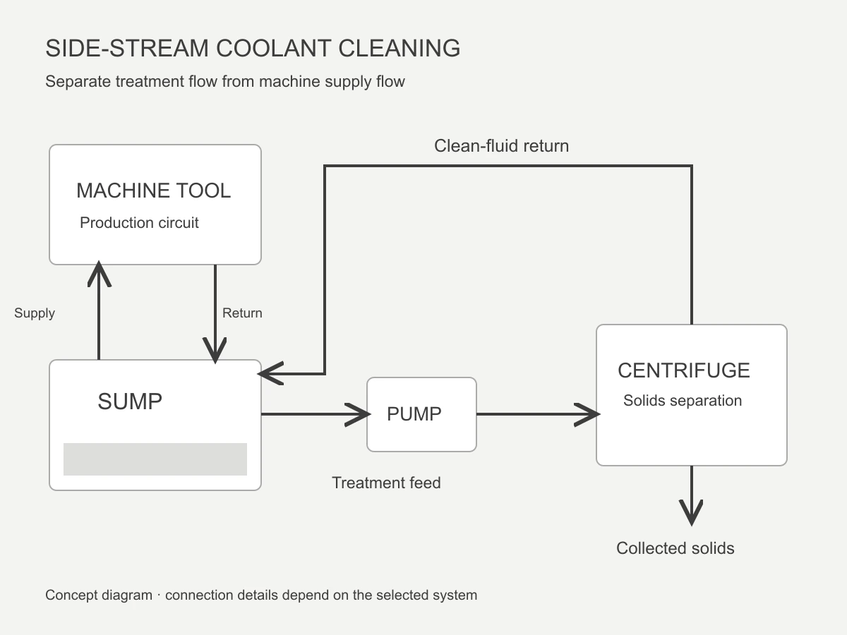
Use a Controlled Bypass Loop
In a typical central arrangement, a controlled side stream is taken from the main sump and fed to the centrifuge. The separator removes denser suspended solids, and the treated liquid returns to a location that supports mixing rather than short-circuiting straight back to the suction point.
This bypass approach allows production circulation and clarification to perform different jobs. The machine supply loop maintains pressure and delivery to the process. The treatment loop is adjusted for separation performance, tank turnover and solids handling. Depending on the plant, coarse screening may be placed ahead of the centrifuge to stop long chips or large swarf from reaching the feed pump.
Good inlet and return positions matter. Poor placement can repeatedly treat the same small volume while leaving settled zones untouched. The final piping arrangement should be confirmed from the sump geometry and operating liquid level.
How the Central Filtration Loop Works
The objective is steady solids control—not a one-time visual cleanup. A practical system separates collection, centrifugal treatment, clean-fluid return and solids discharge into defined operating steps.
Return Fluid to the Sump
Process fluid carries fines back from each machine. Coarse chips should be intercepted before they enter small pumps or narrow pipework.
Control Treatment Flow
A dedicated pump supplies the centrifuge at a stable rate selected for the fluid, solids and required turnover—not simply the maximum pump rating.
Concentrate Dense Solids
Inside the rotating bowl, particles with sufficient density difference migrate outward and collect in the solids zone while clarified liquid leaves the separator.
Mix Treated Fluid Back
The return stream re-enters the central reservoir. Collected solids are removed according to the discharge design and the actual loading rate.
Size the System Around the Contamination Load
Central sump volume is important, but it is only one sizing input. Two plants with the same tank capacity can require different equipment if one produces light grinding fines and the other receives heavy scale, chips or abrasive sludge. A useful quotation therefore needs the operating conditions below.
Fluid and Temperature
Identify water-based coolant, neat oil or another process liquid, plus the normal and maximum temperature. Viscosity affects particle settling and pump selection.
Solids and Loading
Describe the material, particle form and estimated solids generated per shift. Representative feed and settled samples are more useful than colour alone.
Tank and Operation
Provide sump volume, operating level, machine count, production hours, existing pumps and the longest acceptable interval between solids handling.
VC-1500 or VC-2000 for a Central Sump?
Both models use automatic sludge discharge and are intended for continuous industrial fluid circuits. The choice should be based on required treatment flow and solids capacity, then checked against the actual fluid and contaminant.
| モデル | 定格流量 | Centrifugal force | 流量 | Typical selection direction | 詳細 |
|---|---|---|---|---|---|
| VC-1500 | 150 L/分 | 1,860 G | 8 L | Multi-machine systems where treatment flow is the main sizing driver and solids load is moderate. | View model |
| VC-2000 | 200 L/分 | 1,700 G | 20 L | Central systems with heavier solids loading or a longer required interval between discharge events. | View model |
Rated flow is not a guarantee that every fluid can be processed at that rate. Viscosity, particle properties, feed condition and the required separation result may require a lower operating flow or a sample test.
What a Centrifugal System Does—and Does Not Do
A centrifuge is strongest when the process problem is suspended solid contamination with enough density difference from the liquid. It can reduce the solids that continue circulating through the sump without consuming paper or filter bags.
It is not a universal replacement for every coolant-management step. Long chips and large swarf may need screening. Free tramp oil may need coalescence or skimming. Dissolved contamination, bacteria, depleted additives and unstable concentration require their own monitoring and corrective actions. Very light particles or difficult emulsions may also need application testing or a combined treatment train.
For that reason, the system should be specified as part of the process, not as an isolated machine. The best proposal may include pre-screening, controlled bypass flow, temperature monitoring and a defined solids-handling procedure.
Review the Selection Guide- Suitable density difference between solids and liquid
- Representative sample available for difficult fines
- Coarse chips protected by screening where required
- Inlet and return locations prevent short-circuiting
- Discharge and maintenance access included in the layout
- Fluid chemistry managed separately from solids removal
Confirm the Central Sump Installation
Before selecting the equipment, map the existing tank, supply and return piping, available floor space and service access. The centrifuge needs a stable foundation, safe electrical connection, feed and return lines, and enough clearance for inspection and solids handling. If the central system cannot stop, the plant should also define how isolation, bypass and maintenance will be handled without disrupting production.
Hydraulic Layout
Tank dimensions, liquid level, suction location, return position, pump head, pipe sizes and the risk of foaming or air entrainment.
Utilities and Space
Available voltage, floor loading, drainage, access routes, working clearance and environmental conditions around the system.
Operating Plan
Production hours, cleaning windows, discharge collection, operator checks, spare-parts access and the person responsible for routine inspection.
Send Us Your Central Sump Conditions
Share the fluid type, sump volume, machine count, operating temperature, contaminant description, estimated solids load and current piping layout. We will use those inputs to review the treatment loop and recommend whether VC-1500, VC-2000 or another configuration should be evaluated.
Request a System Recommendation View Automatic Discharge Series