
Application · B4

Tapping Oil Filtration

Keep fine chips and sludge from recirculating through thread-cutting operations, without confusing fine filtration with bulk chip removal.

Assess Your Tapping Oil

Tapping Produces Chips as Well as Fine Contamination

Tapping oil filtration begins with the material entering the lubricant circuit. Cutting taps create chips as they form internal threads. Small fragments and wear particles can pass beyond the machine's initial chip collection, while settled material accumulates in quiet areas of the sump. A circuit that looks acceptable at the start of a shift may carry a different solids load after repeated production cycles.

Form tapping is a different operation: it forms threads by displacement rather than cutting them in the same way. It can still introduce wear debris and incoming surface contamination, but its chip burden should not be assumed to match a cutting-tap process. Identify the actual operation before selecting a screen, pump or fine-separation stage.

Record the workpiece material, thread size range, machine count and whether the system uses neat oil or a water-mix tapping fluid. Mixed production can introduce contaminants with different shapes and settling behaviour. The practical target is to control the fraction that remains in circulation after normal chip removal, not to send every chip through a centrifuge.
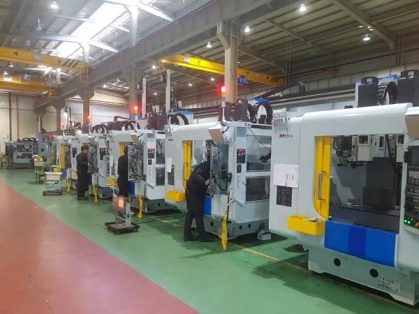
A row of enclosed machine tools in an industrial workshop

Separate Tooling Problems from Fluid Problems

Fine contamination is one possible contributor to an unstable tapping process. It should be investigated alongside tap selection, alignment, speed, feed, lubrication delivery and chip evacuation. Filtration does not correct a damaged tap, an unsuitable cutting condition or an obstructed oil nozzle. Treating every broken tool as a filtration failure can lead to an expensive but ineffective modification.

Use production records to define the concern. Is the plant seeing more frequent sump cleaning, fine debris at the oil return, restricted delivery or inconsistent thread appearance? Compare these observations with tool changes and material batches. Establishing a baseline helps show whether cleaner circulating oil addresses the actual problem.

Avoid promising a fixed improvement in tool life before a controlled comparison. Tool performance should be reviewed using similar parts, tooling and operating conditions. The separation system can reduce a measured solids burden; the resulting production benefit depends on the rest of the process remaining under control.

Use Coarse Removal Before Fine Separation

A staged tapping-oil circuit
StageMain jobDesign question
Machine chip collectionRemove bulk chips and fragmentsCan long or curled chips bypass the collection point?
Feed protectionKeep unsuitable debris out of the pumpWhat screen and service access are needed?
Fine separationReduce suitable suspended finesWhat treatment flow works with the actual oil?
Return to sumpReintroduce treated oilWill the return mix with the circuit rather than short-circuit to suction?

A fine separator should not become the first barrier against stringy swarf. Review the existing conveyor, basket or screen before adding equipment. A persistent coarse-chip bypass can overload the feed arrangement and make a good fine-separation concept unreliable in daily operation.

Where Centrifugal Separation Fits

A centrifuge applies rotational force to the oil and suspended solids. Suitable denser particles collect in the solids region while clarified oil returns to the circulation system. This avoids disposable filter paper within the centrifugal stage, although the complete machine circuit may still include screens or other protective components.

Oil viscosity, operating temperature, particle characteristics and treatment flow determine how the separator behaves. A flow rating is not a universal fine-particle removal specification. High-viscosity thread-cutting oils may need a different operating flow from a less viscous coolant, and the chosen setting should be supported by a representative trial.

Separation does not replenish lubricant additives or restore degraded oil. If the issue is unsuitable chemistry, water contamination or an incorrect fluid concentration, involve the fluid supplier and select the appropriate corrective action. Compare the different maintenance demands in centrifuge versus paper band filter before committing to a treatment method.

Start Model Selection with the Oil Sample

For a dedicated tapping circuit, the VC-600 provides a high-force reference for evaluation: 60 L/min rated flow, 6,500 G and 2 L solids capacity. A multi-machine circuit may lead to assessment of the VC-1500, rated at 150 L/min, 1,860 G and 8 L solids capacity. These are equipment specifications, not promised tapping-oil treatment rates.

The higher-flow model is not automatically the better fine-particle choice. A smaller system operating at an appropriate test-supported flow may address a dedicated sump, while a larger circulation arrangement must also account for sustained solids generation and discharge. Review the automatic discharge series for the operating approach.

Kullanın VC-600 product page ve VC-1500 product page to compare the published equipment data. Final sizing should follow the oil conditions and solids-handling requirements rather than matching the separator nameplate flow to the machine pump.

Trial the Fine Fraction, Then Check the Whole Circuit

Collect oil during representative production, using the site's safe sampling method. Include information about the workpiece alloy, fluid product, normal temperature and any surface treatment entering with the parts. A sample skimmed from an unusually clean surface may miss the contamination that causes the maintenance problem.

During a trial, record feed condition, test flow, collected material and the selected outlet measurement. Where thread quality is the business concern, arrange a production comparison with consistent tooling and cutting conditions. Do not treat a change in liquid colour alone as evidence that a thread tolerance or tool-life target has been achieved.
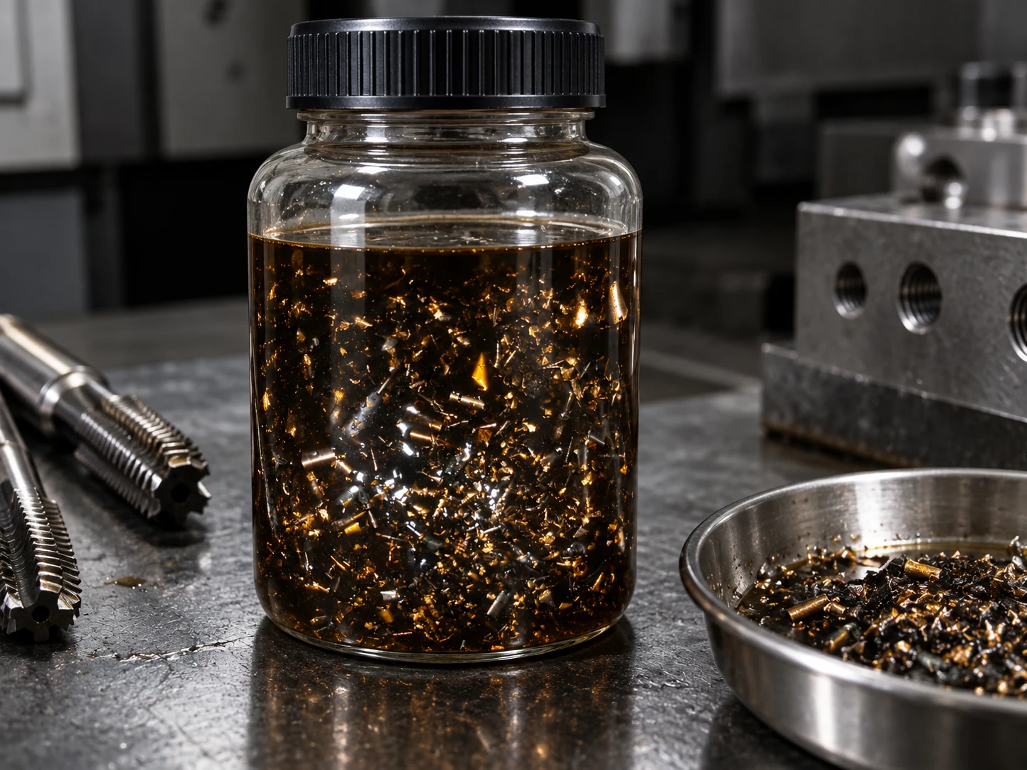
Oil sample containing metal chips beside threading tools

Plan Cleaning Access Before Installation

The separator needs access for inspection, service and collection-container changes. Route hoses so they do not create trip hazards or obstruct the tapping machine's tool-change area. Confirm the feed pump, return path and safe response to a full collection container as part of the installation review.

Keep an operating log that distinguishes normal chip removal from fine-separator cleaning. If the machine sump still fills rapidly, inspect whether settled zones are reaching the treatment stream and whether the process load has changed. The aim is a repeatable maintenance routine rather than an unsupported claim that sump cleaning will disappear.

For upstream forming contamination, see soğuk başlı yağ filtreleme. For the neighbouring thread-forming process, see thread rolling oil filtration. These applications share some lubricant-handling issues, but their contamination sources should be assessed independently.

Assess Your Tapping Oil

Share the workpiece material, oil type, sump volume, normal temperature and chip-handling arrangement. We will review the appropriate separation route and test conditions.

Send Application Details
Üste Kaydır